
How Does a Drill Press Work | The Core Mechanism Explained
This post contains affiliate links. As an Amazon Associate, we earn from qualifying purchases.
A drill press works by converting an electric motor’s rotation into precise vertical drilling force. The motor turns a pulley system, which spins the spindle and chuck at a controlled speed. You lower the spinning drill bit into the workpiece using a feed lever, with the machine’s rigid frame ensuring perfect perpendicular holes. Speed and torque are adjusted by changing the belt position on the pulleys or via an electronic variable-speed control.
That rigid frame is the whole point. A hand drill wobbles. Your arm tires. The angle drifts. A drill press locks the bit in a straight line, every single time, because the head, column, and table are a single anchored unit.
What follows is the anatomy of that reliability. We’ll trace the power from the motor to the hole in your workpiece, name every critical part using specs from real manuals, and explain why getting the speed wrong burns out bits faster than you can buy them.
Key Takeaways
- The motor drives a pulley and V-belt system that spins the spindle; changing the belt’s position on the stepped pulleys changes the drilling speed and torque.
- The quill is the hollow sleeve that moves up and down; the spindle rotates inside it. This separation allows for precise vertical feed without rotational play.
- Speed dictates everything. Drilling steel at 3,000 RPM will blue and ruin a bit in seconds, while drilling hardwood at 200 RPM will burn it. The material and bit diameter choose the speed.
- Incorrect belt tension is the most common mechanical fault. Too loose, and the belt slips under load, burning itself and stalling the cut. Too tight, and you overload the motor and spindle bearings.
- For most home shops, a 5/8-inch chuck capacity drill press with a 1/2 HP motor handles 90% of tasks. Stepping up to a 1 HP model like the Ellis 9400 is for daily metalwork.
The Core Mechanism: From Motor to Bit
A [drill press](https://powertoolguide.A drill press is a simple, brutal gear reduction system built for one job: turn round and round, straight up and down.
The power path is always the same. An electric motor spins a drive pulley. A V-belt connects that to a larger driven pulley on the spindle. That pulley ratio determines the final speed. A 1,720 RPM motor (common for 60Hz AC) driving a pulley half its size spins the spindle at roughly 3,440 RPM. The manual for the Rikon 30-140 confirms this, listing a motor speed of 1,720 RPM and a spindle range of 620–3,100 RPM across five pulley settings.
The spindle rotates inside the non-rotating quill. This separation is critical, the quill’s linear ball bearings provide the smooth, wobble-free vertical travel, while the spindle’s tapered roller bearings handle only the rotational load. Mix those functions, and you get runout.
The chuck mounts to the end of the spindle, typically via a Jacobs Taper (like JT3) or a Morse Taper (like MT2). That taper is a friction fit; knocking it out requires a drift key. The chuck’s three self-centering jaws grip the drill bit’s shank. This entire rotating assembly, motor, pulleys, belt, spindle, chuck, is housed in the head, which is clamped immovably to the vertical column.
The table and base are also clamped to that same column. This creates a rigid triangle between the tool, the workpiece, and the floor. When you pull the feed lever, you’re moving the entire rotating assembly down a fixed, perpendicular path. Your only job is to apply steady pressure. The machine handles the alignment.
Speed Control: The Heart of the Operation
You don’t drill everything at the same speed. Aluminum wants to go fast. Steel needs to go slow. A 1/4-inch bit can spin quicker than a 1-inch bit without overheating. Getting this wrong doesn’t just make a bad hole; it destroys tools.
There are two main systems for controlling speed: stepped pulleys and variable-speed drives.
Stepped Pulleys (Manual Speed Change)
Most bench-top and many floor models use this classic system. The motor pulley and the spindle pulley each have three or four different diameters, or “steps.” The V-belt connects one step on the motor to one step on the spindle.
| Belt Position | Effect on Speed | Effect on Torque | Best For |
|---|---|---|---|
| Motor: Small Step / Spindle: Large Step | Lowest Speed | Highest Torque | Large drill bits (>1/2″), hard metals (steel), threading |
| Motor: Large Step / Spindle: Small Step | Highest Speed | Lowest Torque | Small drill bits (<1/4″), soft materials (wood, plastic) |
| Middle Steps | Moderate Speed & Torque | Balanced performance | General-purpose drilling, mid-size bits |
Changing speed means turning off the machine, loosening the motor tension, and manually moving the belt to a different step pair. The Micro-Mark #81631 manual specifies the technique: “Move the belt to a smaller pulley first, then, while turning the pulley shaft, relocate the other end.” This prevents pinching the belt.
Variable-Speed Drills (Electronic Control)
Higher-end models like the Ellis 9400 VARIABLE SPEED DRILL PRESS replace the stepped pulleys with a single-groove pulley and an electronic controller. A dial or digital readout lets you adjust the motor’s RPM from zero to its maximum while the machine runs. The Ellis manual lists distinct ranges: High Speed (0-1265 RPM), Mid-Range Torque (0-930 RPM), and High Torque (0-570 RPM). This is for serious metalworking.
The rule of thumb never changes: larger diameter or harder material equals slower speed. The Argonne National Laboratory drill press guide reinforces this, noting low range is for larger holes or harder materials, while high range is for small holes and softer materials.
Critical Components and What They Do
Knowing the names is how you diagnose a problem over the phone or follow a manual.
- Head: The main casting that houses the motor, pulleys, and spindle assembly. It clamps to the column.
- Column: The vertical steel post. Everything, head, table, base, references this single axis of alignment.
- Quill: The precision-ground sleeve that moves up and down. The spindle rotates inside it. Its travel length (e.g., 3-1/8″ on the Rikon 30-140) determines maximum hole depth without moving the workpiece.
- Spindle: The rotating shaft that transmits power from the pulleys to the chuck. Its internal taper (MT2, MT3) accepts the chuck arbor.
- Chuck: The three-jaw vise that holds the drill bit. Keyed chucks are most common; keyless chucks exist but offer less gripping force.
- Feed Lever (or Handle): The lever you pull to lower the quill and spindle. It engages a rack-and-pinion gear inside the head.
- Depth Stop: A threaded rod with a locking nut that limits the quill’s downward travel. Set it to drill repeatable blind holes to an exact depth.
- Table: The work surface. It should rotate, tilt (often 45° left and right), and move up/down the column. It must be clamped securely for operation.
- Base: The heavy foot that anchors the machine to the floor or bench. Stability here eliminates vibration.
Where this goes sideways: Using the depth stop as a physical hammering block. You lower the quill until it slams into the stop nut at full force. Do this a few dozen times and you’ll mushroom the stop threads or crack the casting around the quill housing. The stop is a limiter, not a bumper.
How to Operate a Drill Press Safely
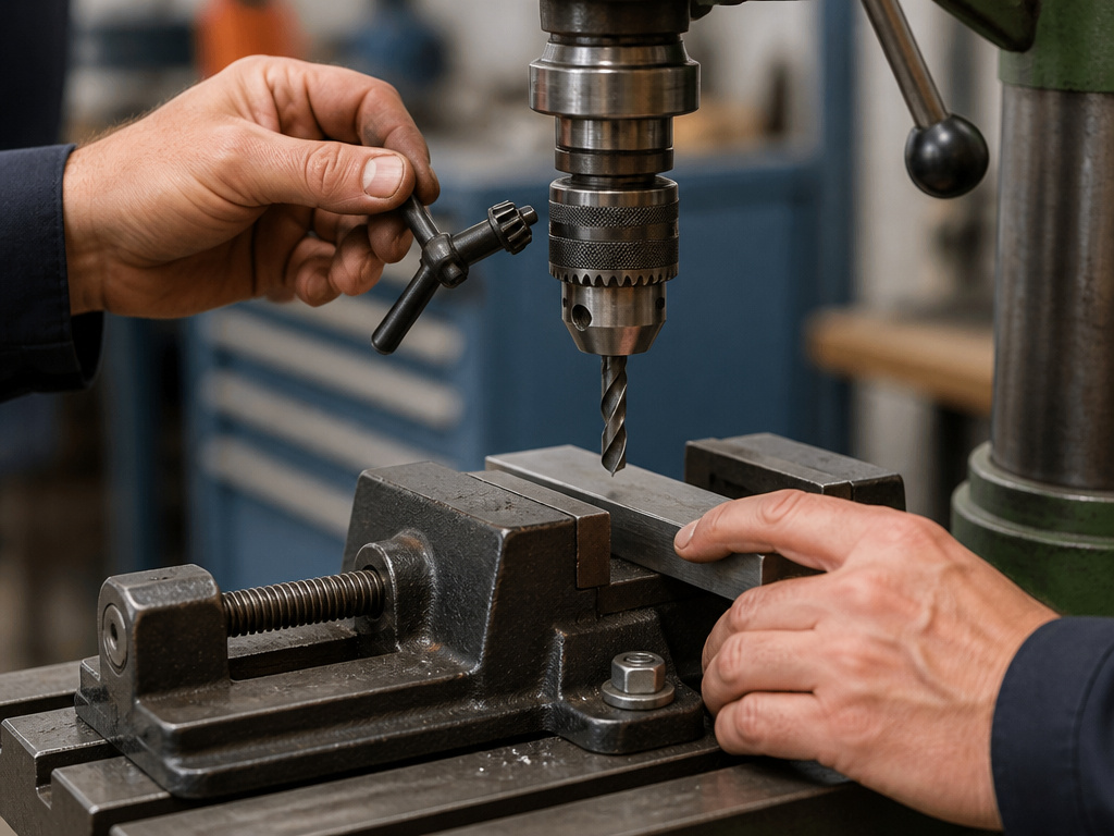 Safety on a drill press involves eliminating the possibility of an accident through procedure. The OSHA drill press trainer script is unambiguous on the primary hazards: contact at the point of operation and rotational entanglement.
Before You Start: The Non-Negotiables
- Eye Protection: Safety glasses, always. A broken carbide tip or a long steel chip travels at eye level.
- Secure the Workpiece: Every time. Use a drill press vise, clamp it to the table, or bolt it down. Your hand is not a clamp. A spinning workpiece becomes a blunt weapon.
- Remove Chuck Key: The self-ejecting key is a good start, but make it a habit. A chuck key left in place becomes a projectile.
- Check Guards: The belt/pulley guard and the magnetic chip shield must be in place. The chip shield stops flying debris without blocking your view.
The Step-by-Step Process
- Select and Insert the Bit: Match the bit to the material. Loosen the chuck jaws, insert the bit shank fully, and tighten securely with the key. Remove the key.
- Secure and Position the Workpiece: Clamp it in a vise, then clamp the vise to the table. Position the hole under the bit by loosening the table lock and sliding the workpiece.
- Set the Speed: Refer to a speed chart. For manual pulleys, change the belt. For variable speed, dial it in. When in doubt, start slower.
- Set the Depth Stop (if needed): Lower the bit to touch the workpiece. Lock the quill at that height. Thread the depth stop nut down to meet the stop collar and lock it.
- Start the Drill and Feed: Turn on the machine. Let the spindle reach full speed. Use the feed lever to apply steady, moderate pressure.
- Clear Chips and Finish: For deep holes, periodically retract the bit to clear chips, which keeps the bit cool and prevents binding. When the depth stop hits, retract the bit fully before turning off the machine.
Easy to miss: The sound of the motor. A healthy drill press has a consistent hum under load. If the pitch drops suddenly and the motor groans, you’re feeding too fast or the speed is too low for the bit size. That groan is the belt starting to slip, ease up immediately.
Drill Press vs. Hand Drill: When to Use Each
 This represents a division of labor. Each tool has a home territory, and smart shops have both.
| Factor | Drill Press | Hand Drill (Cordless Drill/Driver) |
|---|---|---|
| Hole Accuracy | Perfectly perpendicular, repeatable holes. Essential for dowels, metal fabrication, precise layouts. | Subject to user skill and fatigue. Angles drift, especially over multiple holes. |
| Power & Torque | Higher sustained torque via belt reduction. Can drive large Forstner bits or hole saws in hardwood without stalling. | High instant torque (in impact drivers), but motors overheat under continuous heavy load. |
| Operator Control | Two-handed operation on the feed lever allows perfect downward pressure control. Frees you to focus on alignment. | Requires managing both alignment and pressure with your arms and body. Tiring for precise work. |
| Best Use Cases | Drilling metal, accurate wood joinery, repetitive production work, using mortising attachments, drum sanding. | On-site construction, drilling in tight spaces, driving screws, quick holes where absolute precision isn’t critical. |
If you need one hole in a wall stud, grab your hand drill. If you need ten identical, perfectly vertical 3/8-inch holes in a steel bracket, you need a drill press. The former is about convenience and portability; the latter is about precision and repeatability. For understanding the core mechanics of the handheld tool, our guide on how a drill works covers the fundamentals.
Troubleshooting Common Drill Press Problems
A drill press is simple, so its failures are usually loud and obvious.
Problem: Drill Bit Wobbles or Runs Out
- Likely Cause: The bit isn’t seated squarely in the chuck, the chuck jaws are worn, or the spindle/arbor taper is damaged.
- Fix: Remove the bit, clean the chuck jaws and bit shank, and re-seat it tightly. For persistent wobble, check the chuck by inserting a known-straight rod. If the chuck is bad, it must be replaced. See our detailed steps for safe chuck removal process.
Problem: Machine Vibrates Excessively
- Cause 1: Unbalanced pulley. A chunk of missing rubber on a V-belt pulley throws the whole assembly off.
- Cause 2: Loose head or table clamp. The entire head or table is shifting on the column.
- Cause 3: Workpiece or vise not secured. The vibration is coming from the work, not the machine.
- Fix: Tighten every clamp on the column. Ensure the workpiece is solid. Inspect pulleys for damage.
Problem: Belt Squeals or Slips Under Load
- Cause: Incorrect belt tension. This is the #1 mechanical issue.
- Fix: Adjust the motor tension. The Buffalo Tools DP16UL manual gives the spec: tension is correct when the belts deflect about 1/2 inch at their center with moderate thumb pressure. Too tight strains bearings; too loose causes slip and heat.
Problem: Quill Doesn’t Return Fully
- Cause: Weak or broken quill return spring, or gummed-up quill housing from lack of lubrication.
- Fix: Disconnect power. Manually raise the quill and see if it drops. If it falls, the spring is broken. If it’s stiff, clean the quill with a degreaser and apply light machine oil (not grease) to the exposed shaft.
Frequently Asked Questions
What is the “swing” on a drill press?
The swing is twice the distance from the center of the spindle to the front of the column. A “10-inch swing” means you can center a drill bit over a workpiece that is 10 inches in diameter. It defines the maximum width of material you can work with. It’s a critical spec when choosing a machine, which our article on drill press swing measurement explains in detail.
Can I use a drill press as a milling machine?
No. Do not attempt this. A drill press is designed for vertical, downward force. A milling machine is built for sideways (lateral) cutting forces. Applying those forces to a drill press spindle will destroy its bearings, cause catastrophic tool breakage, and likely injure you. The rigidity and spindle design are entirely different. For a full breakdown, read our drill press and milling machine comparison.
How do I change the speed on a drill press without variable speed?
You change the position of the V-belt on the stepped pulleys. Turn off and unplug the machine. Loosen the motor mounting bolts to relieve belt tension. Move the belt to the desired step combination (refer to the RPM chart on the inside of the belt guard). Re-tension the belt and tighten the motor bolts.
What size drill press do I need for a home workshop?
For 90% of home DIY, a bench-top model with a 5/8-inch chuck capacity and a 1/2 to 3/4 HP motor is sufficient. It will handle wood, plastic, and light metal duty. If you regularly drill steel or thick hardwood, step up to a floor model with a 1 HP motor, like the WEN 4214 or the Jet JDP-17MF. The extra mass dampens vibration for cleaner cuts in metal.
What’s the difference between a drill press and a magnetic drill?
Magnetic drill press (or mag drill) is a portable drill press with a powerful electromagnetic base. It clamps directly onto vertical or horizontal steel surfaces (like I-beams) to drill large, accurate holes onsite. It’s a specialized tool for steel fabrication and construction, not a general-purpose shop machine. Learn more about its primary uses of a magnetic drill**.
Before You Go
A drill press turns a chaotic, skill-dependent task into a repeatable mechanical process. Its value lies in absolute control. The rigid column, the adjustable table, and the geared feed lever exist to remove you, the variable, from the equation.
Start with speed. Let the material and bit diameter dictate the RPM. Secure your work like it’s trying to escape. Listen to the machine’s sound. A clean cut is almost quiet. Remember, this tool shares core rotational principles with a hammer drill or an impact drill, but its mission is precision, not persuasion.
For the home shop, a solid mid-size model is a lifetime investment. It’s the difference between a wobbly hole you fill with putty and a clean bore that accepts a bearing with a press fit. That’s the whole job.
